- Wet Filament: Prevention, Symptoms & Drying - July 18, 2024
- Sovol SV08 – Best PrusaSlicer Settings & Profile - June 26, 2024
- Sovol SV08 – Best Orca Slicer Settings & Profile - June 26, 2024
Disclosure: Links marked with * are Affiliate Links. I earn from qualifying purchases if you decide to make a purchase through these links – at no additional cost for you!
Calibration is the only way to achieve perfect results with your 3D printer. Even if you achieve relatively good results with premade profiles, you can only eliminate all printing errors with a calibration.
When calibrating an FDM 3D printer, the print bed is leveled, the extruder, the flow rate, the print temperature, the retraction and the print speed are adjusted so that as few print errors as possible occur.
After a brief preparation of your 3D printer for calibration, I’ll show you the steps you can take to make these calibrations.
The goal of this article is to explain how to calibrate your FDM 3D printer as easily as possible, so you can print perfect results as quickly as possible.
(If you’re looking for resin 3D printer calibration, click here.)
Preparations
Check the stability of the 3D printer: For your 3D printer to work accurately, it is important that all axes can move stably. In many 3D printers, the x- and y-axis wheels are loose after transport. Tighten them until neither the print head nor the print bed wobbles.
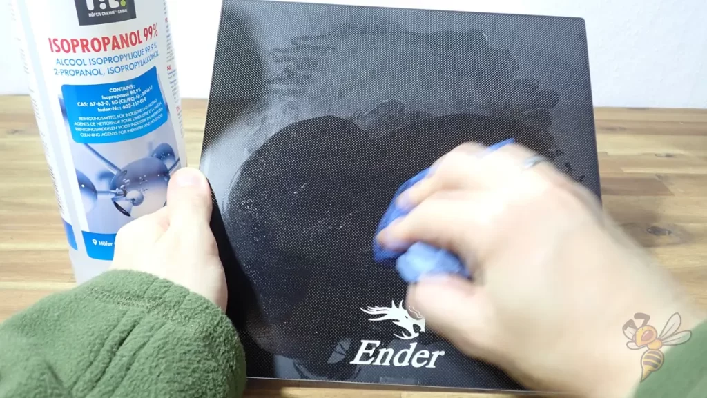
Clean the print bed: In order for the first layer to adhere well to the print bed, it must be free of filament residue, grease/oil or adhesive residue. Here you can find a guide on how to clean your print bed correctly.
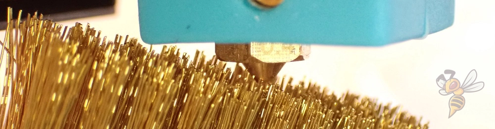
Clean the nozzle: To avoid printing errors during calibration due to a (partially) clogged or dirty nozzle, you should clean it beforehand. If there is no clogging, it is sufficient to wipe it with a paper towel while it is hot. You can find more information here.
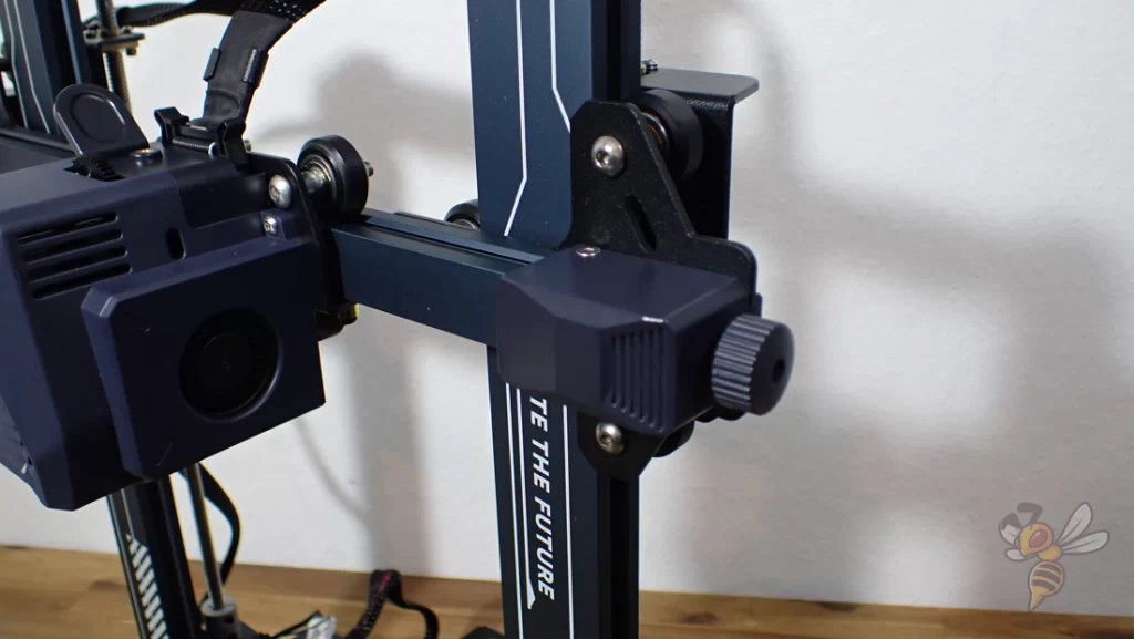
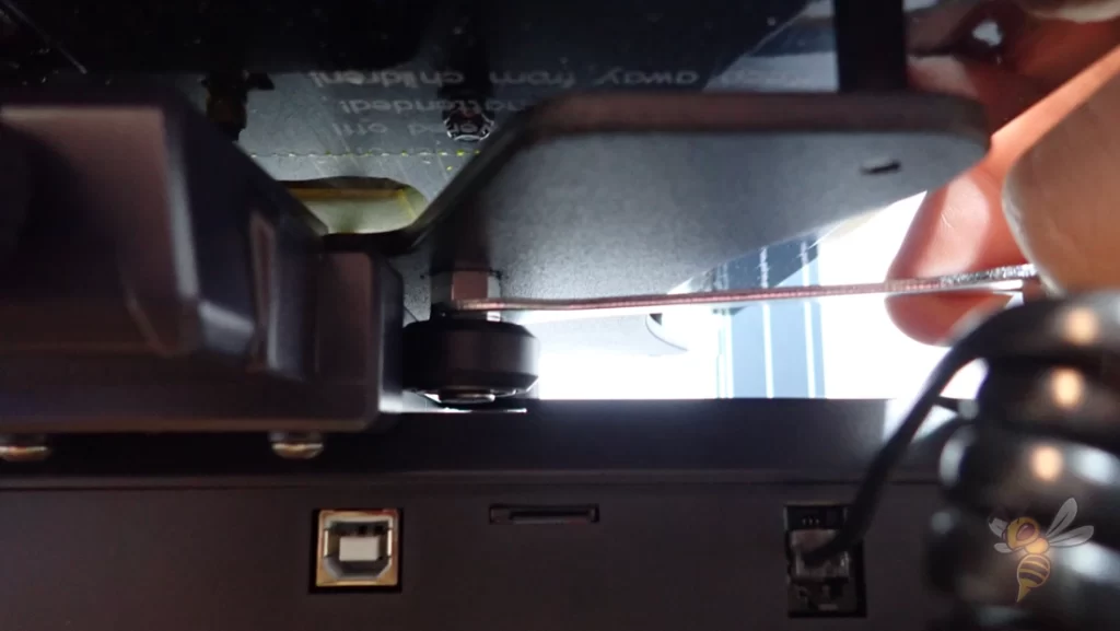
Tension the toothed belts: In order for the x- and y-axis to move properly, their belts must be properly tensioned. If they are too weakly tensioned, they can slip. If the tension is too high, there will be too much friction. The correct tension is approximately reached when the toothed belt emits a high-pitched sound when you pluck it with your finger.
Print Quality Before Calibration
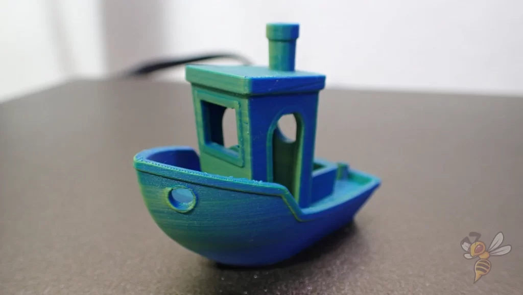
To check the effect of your calibration, it is useful to print a suitable test object before and after calibration. This way, you can best compare the print quality and the behavior of certain print errors.
Suitable test objects are objects that do not test a specific print defect, but rather the general print quality. Here are a few examples of my favorites:
In the course of calibrating your 3D printer, you will use many other objects that specialize in specific settings and print errors.
TIP: Learn how to calibrate your 3D printer to get perfect results every time in my 3D printing course: FDM 3D Printing: The Comprehensive Course from A to Z
(The course teaches everything you need to know for FDM 3D printing in over 60 lessons. The course will get beginners up to my level in no time!)
Print Bed Leveling
Before you can calibrate the settings, the print bed must be properly leveled. Otherwise, the first layer cannot adhere to the print bed correctly.
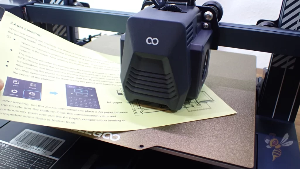
Almost all FDM 3D printers can be leveled using the manual paper method. This is done by adjusting screws under the print bed until the distance between the nozzle and the print bed is the same everywhere on the print bed.
The distance is adjusted so that the paper can be moved with some friction. As a rule of thumb, the friction should be strong enough that you can feel it, but still weak enough that the paper does not curl when you push it toward the nozzle.
The most important thing here is that you set the friction and thus the distance on the print bed the same everywhere. How far away the nozzle actually is, is set by the global z-offset (see below).
There are a few 3D printers that don’t have adjustment screws under the print bed. For these 3D printers, only the z-offset is calibrated. Even for 3D printers with an automatic print bed leveling, a rough manual leveling has to be done first.
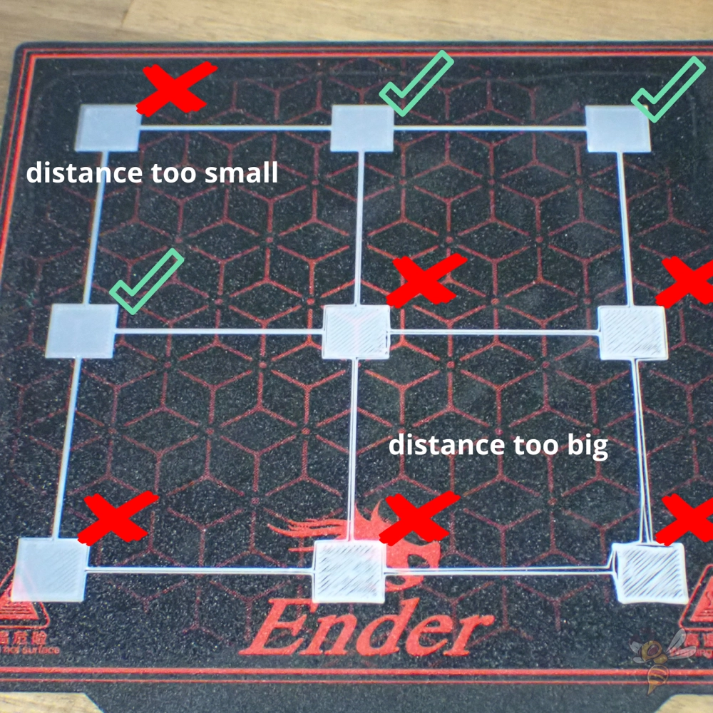
You can test the print bed leveling with a suitable test object. These objects usually consist of thin areas that are evenly distributed over the print bed.
After printing, you can either see by eye whether the distance is too large or too small, or measure the layer height with a caliper gauge. With perfect print bed leveling, the individual areas should be the same thickness everywhere.
You can find test objects for print bed leveling on portals like Thingiverse.
Z-Offset
The print bed leveling was all about eliminating the tilt of the print bed as much as possible. Although you also adjusted the distance of the nozzle to the print bed at different points, the global z-offset still has to be adjusted separately in the center of the print bed.
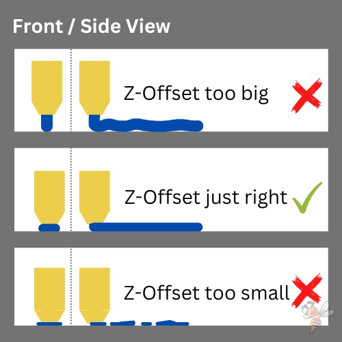
You can adjust the z-offset in two different ways. Either you do this also by feeling with the paper method or you pay attention to how the first layer of a test print is printed in the center of the print bed.
The filament should not be pressed too hard onto the print bed, nor should it be placed loosely on it. If the z-offset is too large, the first layer will not adhere to the print bed and may come off either immediately or during printing. If the z-offset is too small, you can create an elephant foot or prevent extrusion completely.
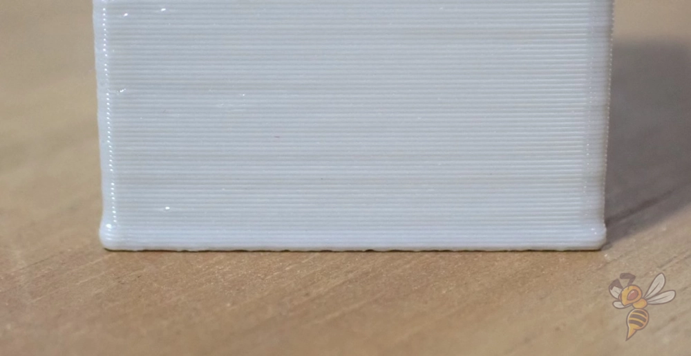
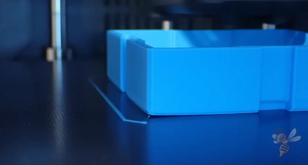
In an elephant foot, the first layers of the object are wider than they should be. It is often caused by a too small z-offset or a too high print bed temperature.
Print Bed Temperature
The print bed temperature is one of the most important settings for good print bed adhesion. If you set it too high, the first layers may be too runny and flow outward too much. If the temperature is too low, the print bed adhesion will be worse.
Depending on how well your 3D printer’s print bed surface is suited for your filament, you’ll have more tolerance for the ideal print bed temperature.
These are good starting values for the print bed temperature of the four standard filaments:
Change these values in small increments of 5 °C in one direction or the other if you observe either an elephant foot or too poor print bed adhesion.
If you only achieve good print bed adhesion at too high temperatures, you should read the essential steps to improve print bed adhesion in this article: 3D Print Not Sticking to the Bed: How to Fix it Step-by-Step
E-Steps
The core of an extruder is the stepper motor. Therefore, extruder calibration is also called E-Steps calibration. Extruder calibration involves checking that the extruder is actually extruding the set amount of filament.
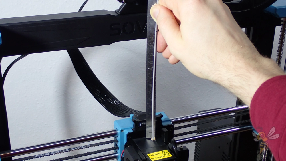
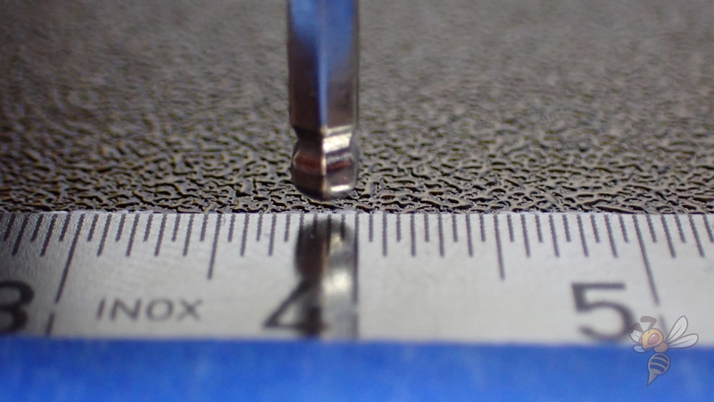
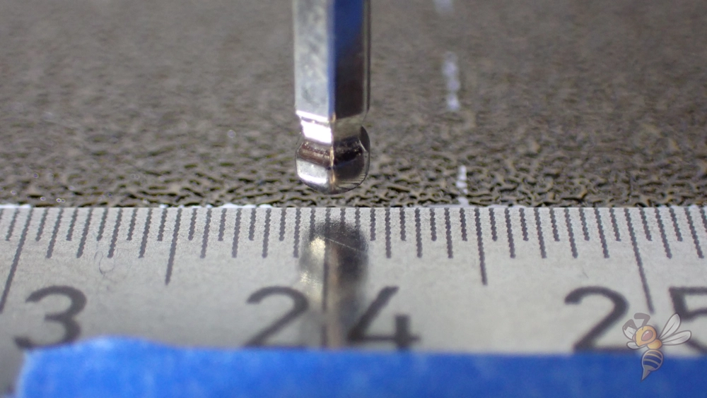
The simplest method for this is to mark the filament before the extruder, extrude a target amount of filament, and determine the actual length of filament that was extruded.
Most 3D printers allow you to adjust the E-Steps in the menu. The number specified defines how many steps the motor requires for one millimeter. If the number is too high, too much filament is extruded and if the value is too low, too little filament is extruded.
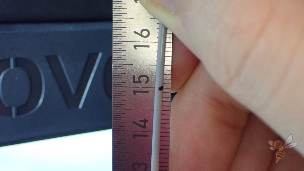
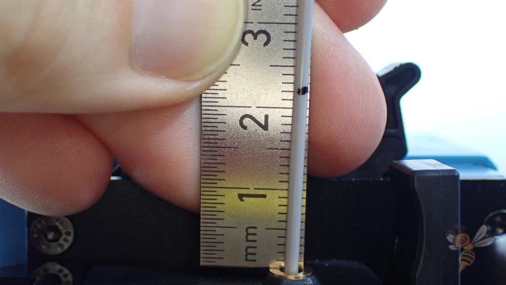
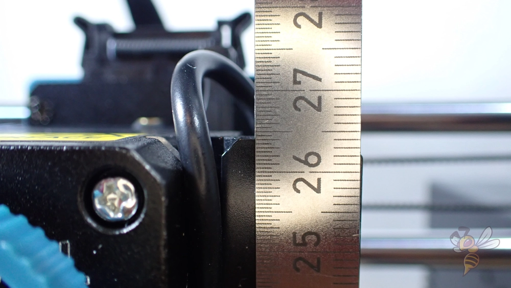
In the example above, I marked the filament 150 mm above the extruder. The 3D printer was supposed to pull in 130 mm of filament, but only pulled in 128 mm. As a result, the mark was 22 mm and not 20 mm. In the menu, 90 E-steps were set. From the measurement, the new value is 91.41. With this value, the 3D printer then extruded the correct amount of filament.
To make it as easy as possible for you, I programmed a small calibration calculator for the E-Steps. You can enter the respective values above and get your new E-Steps.
The more filament you extrude, the more accurate the calculation will be. Since you have a certain reading inaccuracy, but this does not change when you measure a longer distance, the accuracy of the calculation automatically improves.
XYZ-Steps
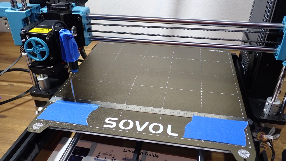
The calibration of the x-, y- and z-axis is similar to the calibration of the extruder. Again, you can use a steel rule to measure the actual distance the extruder has traveled.
For the x- and y-axis, attach the ruler to the print bed along the axis. Pay close attention to a 90° angle to the other axis. You can mount a pointer on the print head so that you can read off the distance traveled as accurately as possible. You can also use the nozzle for this.
Start on the left side of the print bed and move the print head in x-direction via the menu of the 3D printer. The more distance you cover here, the more accurate the calibration will be.
With my 3D printer, I started at 40 mm and was at 241.5 mm after a movement of 200 mm. Thus, the print head has not moved 200 mm in the x-direction, but 201.5 mm. The stepper motor of the x-axis therefore performs too many steps per millimeter and the value must be reduced.
Also for the calibration of the axes I programmed a small calculator for you. Enter here the start point of your measurement, the length of the movement you enter in the menu and the end point of the movement in millimeters. From your previous X/Y/Z steps it will calculate your new steps.
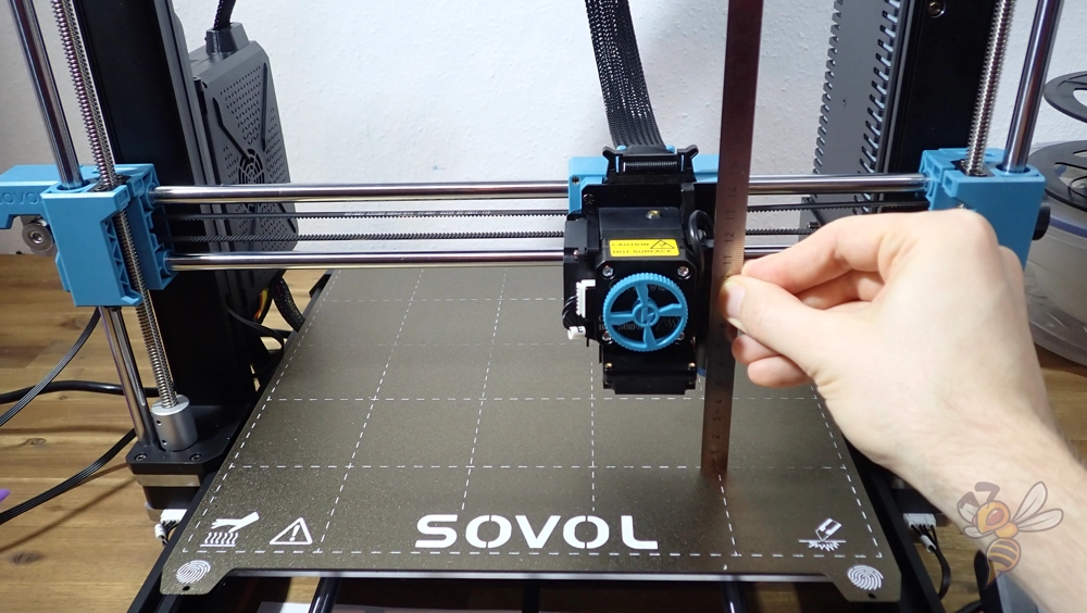
The z-axis can also be calibrated in this way. To do this, move the printhead down and find a place on the printhead where you can measure its height. Then move it up in z-direction, the further the better.
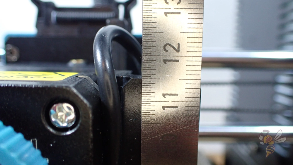
In my case, I moved the printhead up 150 mm in the z-direction. The start point was at 115 mm, the end point at 264 mm. So the target was missed by 1 mm.
When I enter these values into the calculator above, the original 90 steps/mm become 90.6 steps/mm. After entering the new value in the menu, the print head moves exactly to the set height.
Here you can read the full guide: XYZ Calibration of 3D Printer Stepper Motors (+ Calculator)
Flow Rate
The flow rate of a 3D printer indicates how much filament is extruded per second. If this value is set too high, the lines will be wider than they should be and narrower if it is too low. By default, the flow rate is always 100% (or 1.00 in some slicers).
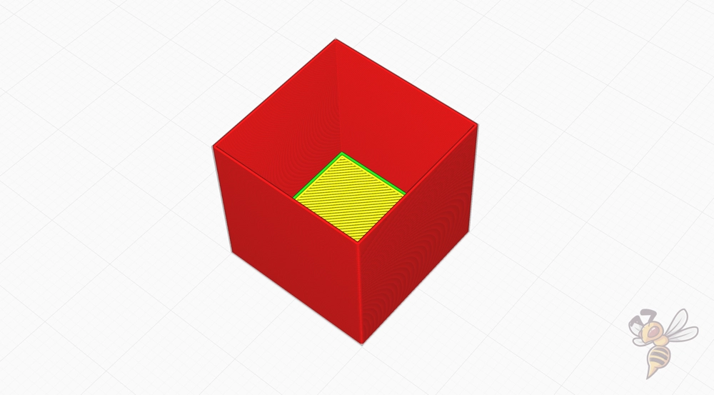
To calibrate the flow rate, a hollow cube printed with a certain wall thickness is suitable. I have created an STL file for this, which you can download here for your calibration.
The cube consists of four side walls and a bottom layer. The walls are each 0.4 mm thick. The line width in your slicer should also be set to 0.4 mm with one wall line.
You can also use a normal cube (e.g. from the Calibration Shapes plugin in Cura) and print it without infill and without top layers. Then note your line width and the number of wall lines.
After printing, measure the actual wall thickness and compare it to the theoretical wall thickness from the slicer. Depending on the direction in which the measured wall thickness deviates, the flow rate must be adjusted accordingly.
I also programmed a small calculator for calibrating the flow rate. Here you can enter your previous flow rate, the theoretical wall thickness from the slicer (consisting of the line width and the number of wall lines) and the measured wall thickness.
To improve the result, you can measure all four sides of the cube and calculate the average of them and enter it above as the measured wall thickness.
After the calculation, the calculator will give you the new flow rate, which should result in the theoretical and measured wall thickness matching. You can confirm this by printing a new cube with the new flow rate.
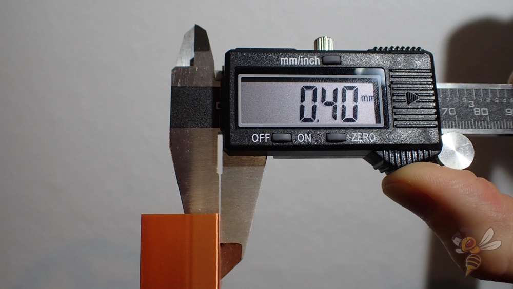
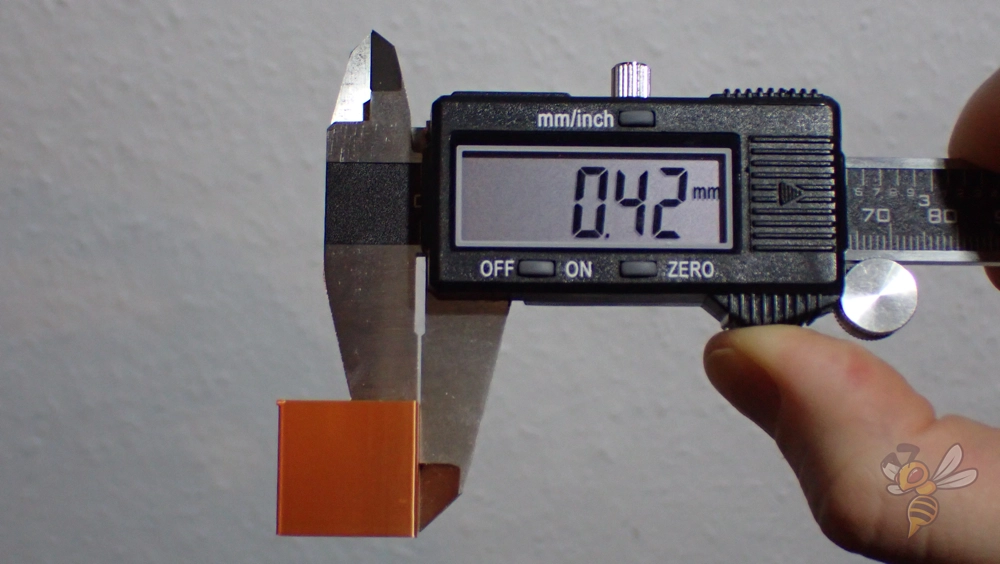
For my 3D printer, a flow rate of 100% resulted in a measured wall thickness of 0.42 mm. After the calculation, the new flow rate should be 95.24%, which then printed the correct wall thickness.
The specification of the flow rate differs depending on the slicer. In Cura and IdeaMaker it is given as a percentage, in PrusaSlicer and Simplify3D as a number. A flow rate of 102% in Cura corresponds to a flow rate of 1.02 in PrusaSlicer.
Print Temperature
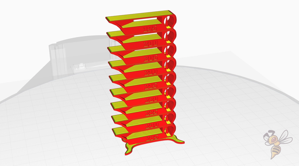
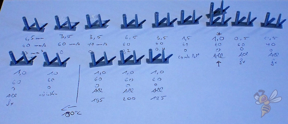
To find the ideal print temperature, you could print an object at different print temperatures and compare their quality. However, it is much more efficient to print a so-called temperature tower.
These test objects consist of several layers of the same geometry, but printed at different printing temperatures. This way, after printing, you can see at a glance at which printing temperature the best results are achieved.
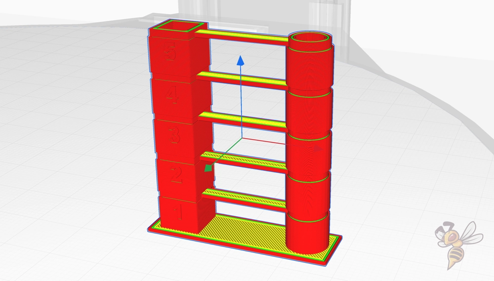
There are many temperature towers available. I like to use this one from gaaZolee on Thingiverse. The design tests various printing errors through clever geometries. In addition to overhangs and bridges, it also tests stringing behavior.
To change the print temperature per layer, you need the appropriate G-code for it. Either you can add this manually to the G-code or you use the slicer functions. In Cura, there are handy scripts for this.
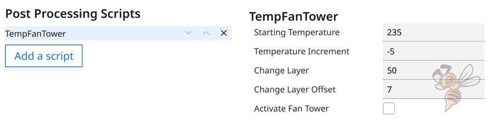
You can either use the standard script ChangeAtZ or the TempFanTower script from the Calibration Shapes plugin. Here you can define at which temperature the tower should start, in which steps the temperature should be changed per layer and after how many layers the temperature should be changed.
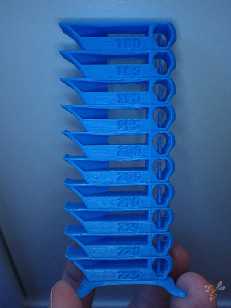
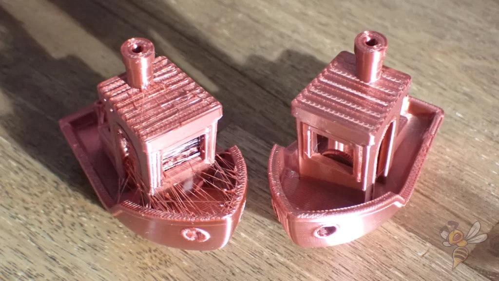
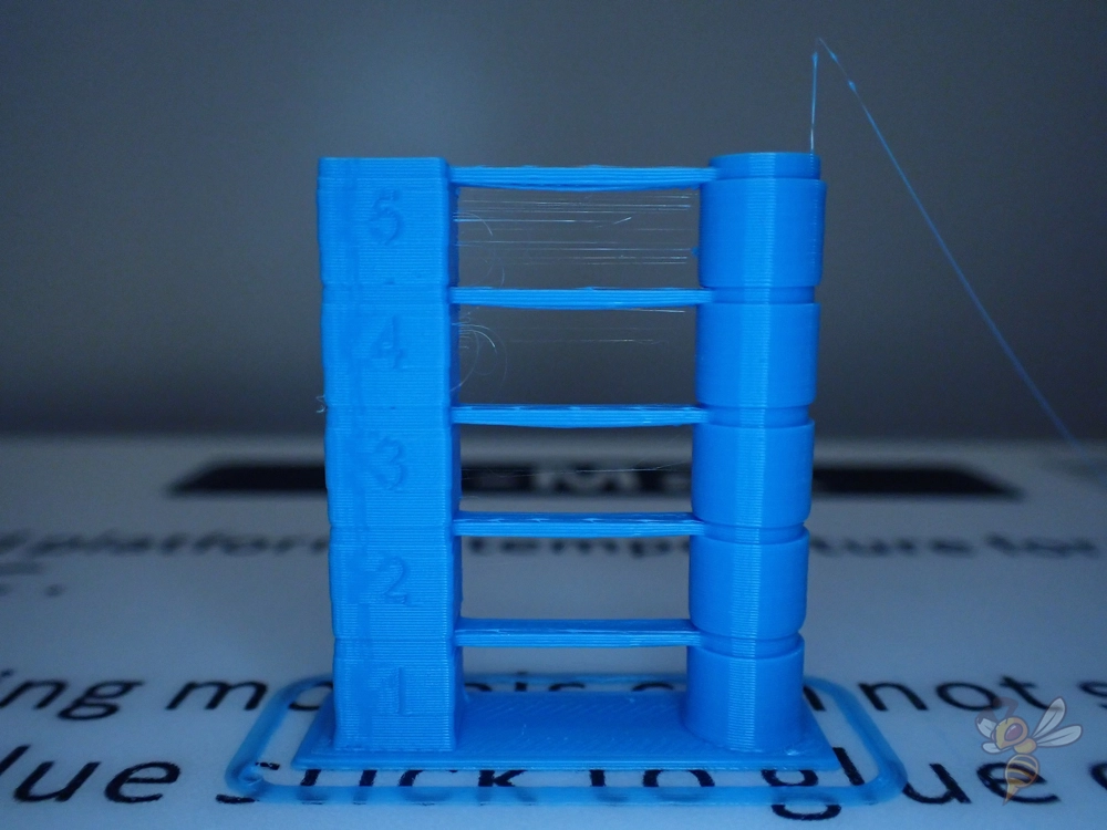
My 3D printer produced the results shown above with a PLA filament. At the high temperatures, there was more stringing and the overhangs were not printed cleanly. Also, you can see that the surface gets glossier as the temperature gets higher.
If you are mainly concerned with high stability and optical printing defects such as stringing are unimportant, a high printing temperature pays off. The higher the printing temperature, the stronger the adhesion of the individual layers to each other.
As you can see, the print temperature and retraction settings are coupled. If you change the print temperature, this has a big influence on stringing and oozing.
Therefore, it makes sense to calibrate the print temperature again after calibrating the retraction, and to calibrate the retraction again afterward. It is normal to calibrate the print temperature and the retraction at least twice to get perfect results.
3D printing can be difficult – especially in the beginning. Many beginners struggle with print errors, poor print bed adhesion, or don’t know how to properly set up the slicer.
That’s why I created an online course to get everyone up to my expert level and as quickly as possible.
The course covers everything you need to know about FDM 3D printing to get perfect results every time. Click the link below to learn more about the content and what to expect (and don’t worry: there are no tests! Learn at your own pace, completely stress-free).
Retraction
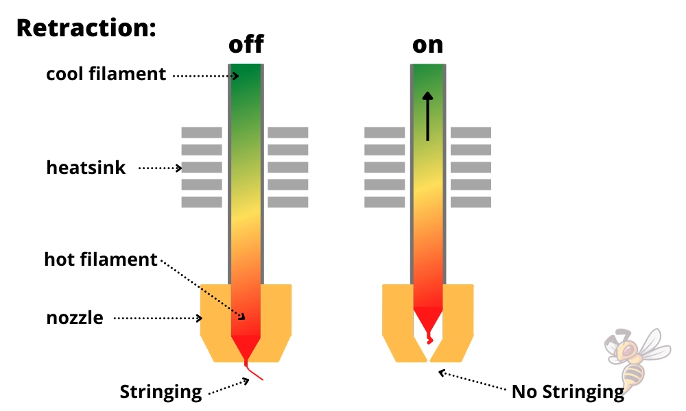
The retraction settings define how the filament is pulled back into the nozzle after an extrusion. It consists of different settings, the most important being the retraction distance and the retraction speed.
If the filament were not pulled back into the nozzle after an extrusion, it would flow out uncontrollably on the way to the next extrusion. The result is either fine hairs between the two points of extrusion (stringing) or blobs (oozing) if a lot of filament has escaped.
When calibrating the retraction, the settings must be calibrated so that neither too much nor too little filament is pulled in. If too much filament is pulled in, it can cause holes or other defects at the start of the next extrusion.
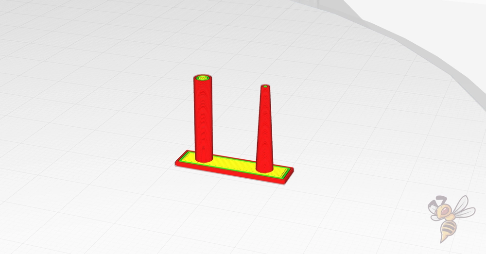
There are various test objects for calibrating retraction. I like to use the test objects from the Calibration Shapes plugin in Cura. There you can find both a retraction tower that works similar to a temperature tower and a small test object that is printed within a few minutes.
There is also a script for the retraction tower where you can adjust the retraction settings for each layer.
As a starting point for the many retraction settings, you can either use the values from a predefined profile of your slicer, or the values given below. The steps in which you should change them must be large enough so that you approach the correct value quickly, but small enough so that you don’t miss it.
Here is an overview of each setting and the usual steps in which you can change them:
- Retraction distance (Bowden extruder): ± 0.4-0.8 mm
- Retraction distance (direct drive extruder): ± 0.1-0.2 mm
- Retraction speed: ± 3-5 mm
When calibrating, make sure that you only change one value at a time. Otherwise, you will not know which change caused the observed effect. Then you could go around in circles longer than necessary until you have found the right settings.
Besides the values given above, there are many other settings for the retraction. If you have not yet been able to eliminate print errors such as stringing by calibrating the retraction and the temperature, you can make these settings next.
Especially when calibrating the retraction, many beginners get frustrated. It may take a few test objects until you find the right settings. Also be aware that the retraction is coupled with the temperature. Alternating calibration of temperature and retraction is the quickest way to get perfect results.
Print Speed
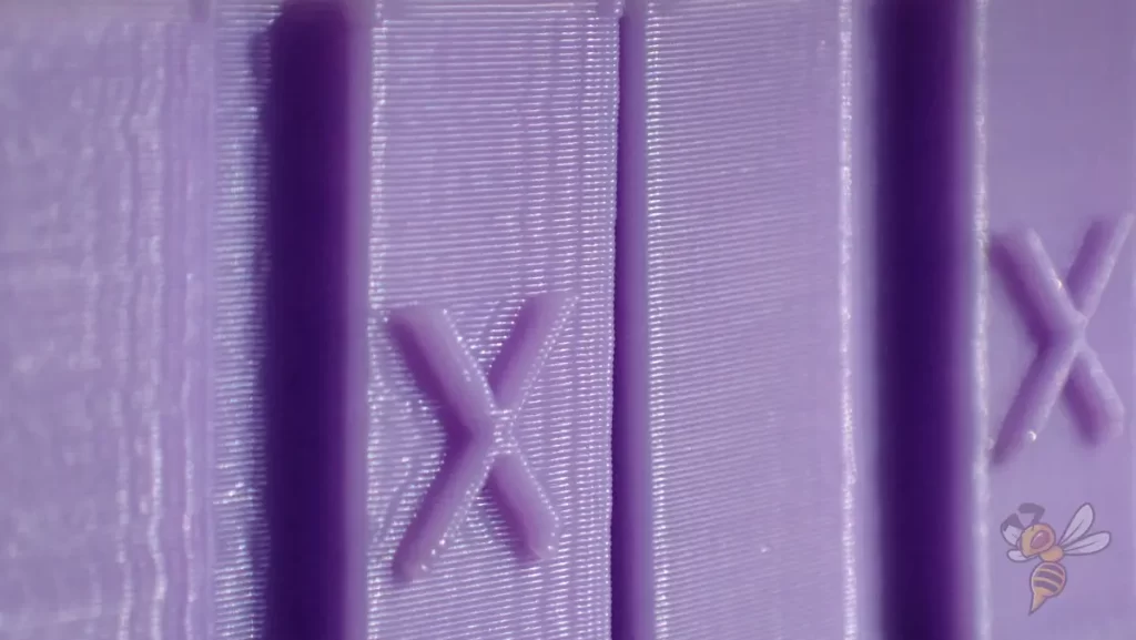
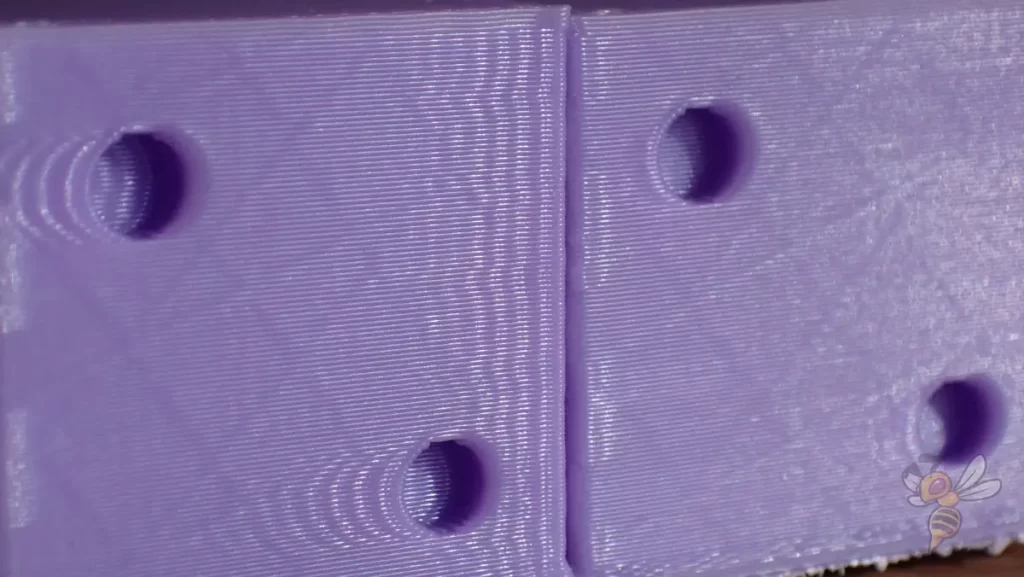
In 3D printing, you want to use a high print speed so the object finishes quickly. But if it’s set too high, various print errors can occur. The error that becomes visible first is called ringing or ghosting.
Vibrations occur every time the print head changes direction. Depending on how stable the 3D printer is and how light or heavy the print head is, these vibrations are sometimes stronger and sometimes weaker. The lighter the print head and the more stable the construction of the 3D printer, the higher print speeds can be achieved.
To calibrate the speed you can also quickly find many test objects, I like to use the ringing test cube from jstevewhite on Thingiverse. The cube has holes in the surface on two sides and letters and valleys on the other two sides.
Basically, you’re trying to set the print speed so high that you can’t see said print errors yet. Depending on how high your tolerance for such printing errors is, the printing speed is sometimes more or sometimes less.
Besides the print speed, there is also the acceleration of the print head. Hereby you have also a big influence on the speed at the edges of the object at changes of the movement direction of the print head. The lower the maximum acceleration, the fewer print errors you will get.
If you want to improve your printing speed or look for other good test objects, you can check this article: 3D Print Speed Test: Files & Optimizations
In said article, you will also find a short introduction to the Klipper firmware. With this software, you can use an accelerometer on the print head to measure and compensate for the vibrations that occur. With this, you can improve your printing speed considerably. I was able to increase print speed from 50 mm/s to 250 mm/s with my Ender 3 V2 without any print errors! Here is the article about it.
Print Quality After Calibration
As described at the beginning of the article, it is worth to test the print quality before and after calibration respectively. If you used the same model, you can compare the performance one-to-one. Then you might notice optimization possibilities that you can improve in a second run.
Disclosure: This website is the property of Martin Lütkemeyer and is operated by Martin Lütkemeyer. Martin Lütkemeyer is a member of the Amazon Services LLC and other Affiliate Programs. These are affiliate advertising programs designed to enable websites to earn advertising revenue through advertising and linking to Amazon.com and others. Links marked with * are affiliate links.