- Wet Filament: Prevention, Symptoms & Drying - July 18, 2024
- Sovol SV08 – Best PrusaSlicer Settings & Profile - June 26, 2024
- Sovol SV08 – Best Orca Slicer Settings & Profile - June 26, 2024
Disclosure: Links marked with * are Affiliate Links. I earn from qualifying purchases if you decide to make a purchase through these links – at no additional cost for you!
The goal of calibrating the stepper motors of the XYZ axes of a 3D printer is to ensure that the nozzle moves in all three directions as far as the slicer expects it to move.
Especially for projects that consist of multiple 3D-printed parts, the dimensions are important. Otherwise, the respective parts will not fit together well. XYZ calibration is one of the essential influences on the dimensional accuracy of your parts.
In this article, I’ll show you step-by-step how to calibrate each axis of your 3D printer and how to check the calibration at the end.
However, there are some other important functions and settings that you should calibrate. Have a look at this article for a detailed guide on how to do it: 3D Printer Calibration: Step-by-Step to Perfect Results
Why You Can Trust This Guide
- I have tested over 50 3D printers.
- I have calibrated each of these 3D printers.
- I perform this calibration regularly on all of my 3D printers.
- So I’ve done the XYZ calibration several hundred times, and with a wide variety of firmwares, menus, and designs.
Accuracy of XYZ Stepper Motor Calibration
| Measuring equipment | Accuracy | Distance | Percentage error (= accuracy/distance) |
|---|---|---|---|
| Ruler | ± 0,5 mm | 200 mm | 0,25% |
| Caliper | ± 0,02 mm | 20 mm | 0,1% |
The calibration differs depending on what kind of measuring equipment you have available. If you have a very accurate caliper at your disposal, you can directly print a calibration cube and measure the length of its edges.
If you do not have a caliper, you can still achieve relatively high accuracy with a ruler. The calibration procedure is still basically the same, you just have to move longer distances so that the percentage error is smaller. In this article, I assume that you do not have a caliper at your disposal.
Step 1: Attach a Ruler to the Axis
The XYZ calibration of your 3D printer is divided into the respective axes. The individual steps are the same.
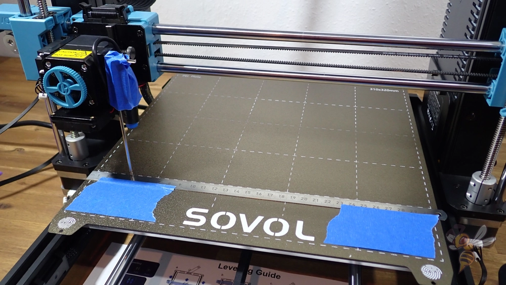
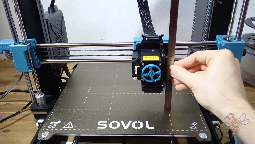
First, you need to attach a ruler along an axis. The best way to calibrate the x and y axes is to attach a ruler to the print bed. Pay close attention to a 90° angle to the other axis.
To measure the moved distance, you also need a pointer of some kind. You can either use the nozzle itself, or you can attach a suitable object to the print head. In the picture above, I have attached an Allen key to the print head.
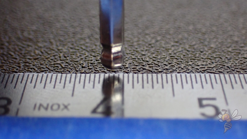
The nozzle or the pointer that you have attached to the printhead should be able to clearly indicate the start position. In the example above, the right edge of the Allen key points to the 4 cm mark of the ruler.
Along the z-axis, you can either attach the ruler to the frame or measure the height of the print head directly.
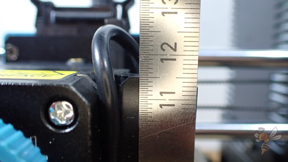
In the example above in the picture, there is a flat surface at the print head where I can place the ruler. It is easy to read the height of the edge relative to the print bed.
Note the starting point of the movement. At the end, you will need this value to calculate the distance covered.
Step 2: Move the Axis via the Menu
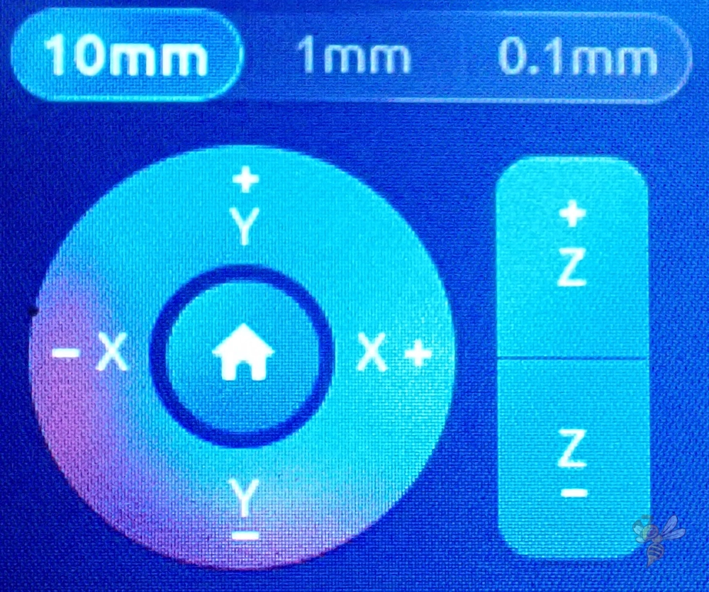
In this step, you move the respective axis by a certain value. Move the axis as far as possible. The longer the distance, the smaller the percentage error of the calibration.
| Distance traveled | Reading accuracy | Percentage error of calibration |
|---|---|---|
| a | c | c/a |
| 5 cm | ± 1 mm | ± 2% |
| 20 cm | ± 1 mm | ± 0,5% |
With many 3D printers, you cannot enter a desired length of the movement. There, you can only move the print head or the print bed in several steps via the buttons in the menu. If the menu does not have a display of the current position, you have to remember the number of steps and multiply it by the step length to get the total distance.
Step 3: Measure the Traveled Distance
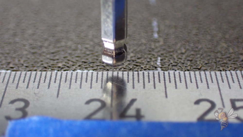
Note the end point of the movement after you have moved the respective axis. From the start point and the end point we calculate the actual distance the nozzle moved in the next step and from that the new XYZ steps.
If you have a caliper, you can now measure the length of the edges of the printed calibration cube and use these values as the distance traveled.
Step 4: Reading the Previous XYZ Steps
The XYZ steps of the stepper motors indicate how many steps the stepper motors move for one unit of length. This is also defined by G-code.
On some 3D printers you can read and change these values directly in the menu. This makes the calibration of the XYZ axes of these 3D printers much faster. With other 3D printers, however, you can neither see nor adjust these values.
If you use OctoPrint for your 3D printer, you can read out and change the settings by certain G-code commands. However, since the installation is quite complex and you only want to change the settings for the stepper motors, the Chrome extensions gcode-sender is better suited for this.
To control your 3D printer with this extension, you have to connect it to your computer via cable. Under the settings in the extension, you can select the respective port. Enter the highest possible baud rate (115200). You should now be able to connect the extension to your 3D printer and control it through it.
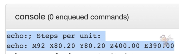
“M501” is the G-code command to read the current settings of the 3D printer.
Among the many output settings you will also find the following lines:
- echo:; Steps per unit:
- echo: M92 X80.20 Y80.20 Z400.00 E390.00
This is the meaning of the relevant parameters:
- X80.20: the current steps per unit length of the X-motor
- Y80.20: the current steps per length unit of the Y-motor
- Z400.00: the current steps per length unit of the Z-motor
- E390.00: the current steps per length unit of the extruder motor (how to calibrate the extruder, you can read here)
Now you have all the values to calculate the new XYZ steps and improve the accuracy of your 3D printer.
Step 5: Calculate the New XYZ Steps
With the measured values and the old values for the XYZ steps, you can use the calculator above to calculate your new XYZ steps. The formula for this is as follows:
previous X/Y/Z-steps * (travel length / (end point - starting point))Or in the case of a calibration cube:
previous X/Y/Z-steps * (theoretical edge length / actual edge length)In our example, the starting point was at 40 mm on the ruler. The length of the movement should be 200 mm and the measured end point was at 241.5 mm. This means that the movement was too far in the x-direction. So, the steps of the X stepper motor of the x-axis are too high. Therefore, the new X steps are lower than before.
The previous X-steps were 80.20 and with the entered values of the movement follow to new X-steps of 79.60.
Step 6: Enter the New XYZ Steps
You can now save the new XYZ steps in your 3D printer via the menu, via OctoPrint or with the gcode-sender.
If you want to do it via G-code, the command is M92. The command is followed by the new parameters that you want to save.
This would be the G-code command to send the new X-steps from our example to the 3D printer:
- M92 X79.60
Repeat this for the other two axes and save the new settings with the M500 command.
If you can’t enter the new XYZ steps in the menu of your 3D printer and you don’t want to change anything manually in the G-code, you can adjust the scaling percentage in the slicer. However, you will have to do this for each print.
Step 7: Check the Calibration
To make sure that the 3D printer has adopted the new settings, you can check them again with the M501 G-Code command.
Then you can move the axis again and compare the distance you entered with the distance you measured. If the nozzle moves relative to the print bed by exactly the entered distance, the calibration is complete.
Step 8: Print and Measure an XYZ Cube
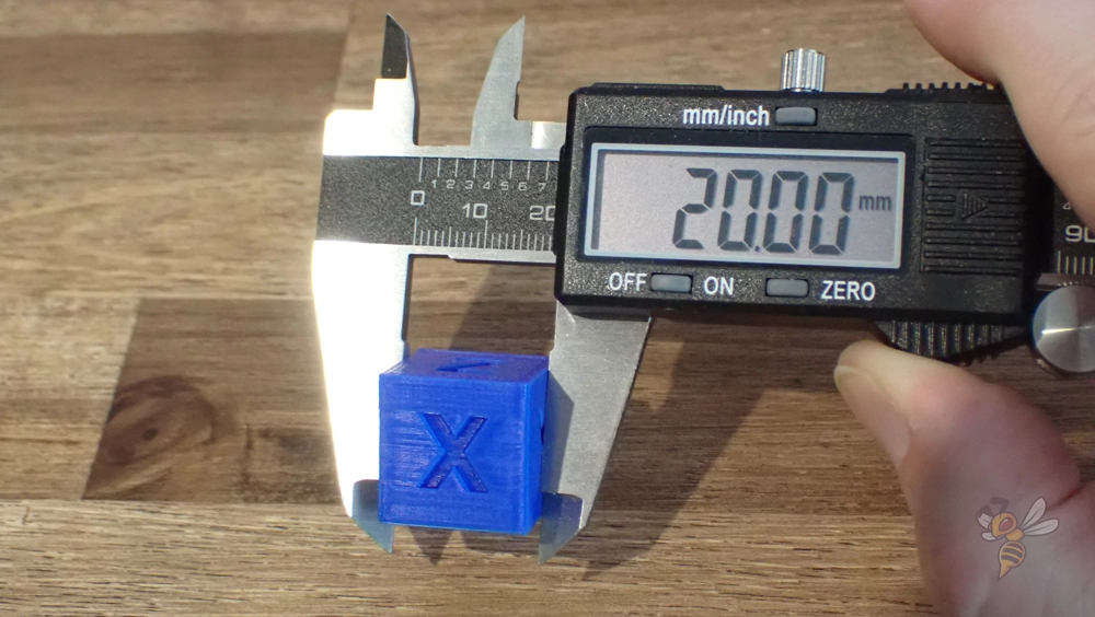
To be on the safe side, I always print a calibration cube after the XYZ calibration and measure the length of its edges with a caliper. The length should be 20 mm. If the calibration was not successful, the measured edge length would be different.
However, when measuring the length of the edges, make sure that you do not include any elephant foot or other printing errors in your measurement. For example, you can measure only the center of the cube or remove the top and bottom layers with a side cutter.
While XYZ calibration is not the only factor affecting the dimensional accuracy of printed parts, it is one of the biggest. This brings you one step closer to accurate parts that you can also use for mechanical applications.
Disclosure: This website is the property of Martin Lütkemeyer and is operated by Martin Lütkemeyer. Martin Lütkemeyer is a member of the Amazon Services LLC and other Affiliate Programs. These are affiliate advertising programs designed to enable websites to earn advertising revenue through advertising and linking to Amazon.com and others. Links marked with * are affiliate links.