- Wet Filament: Prevention, Symptoms & Drying - July 18, 2024
- Sovol SV08 – Best PrusaSlicer Settings & Profile - June 26, 2024
- Sovol SV08 – Best Orca Slicer Settings & Profile - June 26, 2024
Disclosure: Links marked with * are Affiliate Links. I earn from qualifying purchases if you decide to make a purchase through these links – at no additional cost for you!
The printhead settings define the size of the printhead in Cura. If the dimensions of the printhead are changed, the printhead settings must also be adjusted. Then no collisions can occur when printing several objects one at a time.
Although there is a profile with the correct printhead settings for most 3D printers in Cura, you will need to modify this profile when you upgrade the printhead or create your own profile.
For example, if you attach a BL-Touch or CR-Touch to the printhead, the printhead will become larger overall. If you do not update the printhead settings, collisions may occur with certain print jobs.
Such print jobs are, for example, those in which several objects are printed one at a time and not simultaneously.
Table of Contents:
Printing Objects One At A Time
The printhead settings are rarely adjusted. They are only important for special applications. One of these applications is the printing of several objects one after the other in one print job.
If the correct dimensions of the printhead are not stored in Cura, the printhead may collide with already printed objects on the printing plate during printing.
With the correct printhead settings, Cura knows how much space there needs to be between each object to avoid collisions. During printing, the print head then moves around the objects that have already been printed.
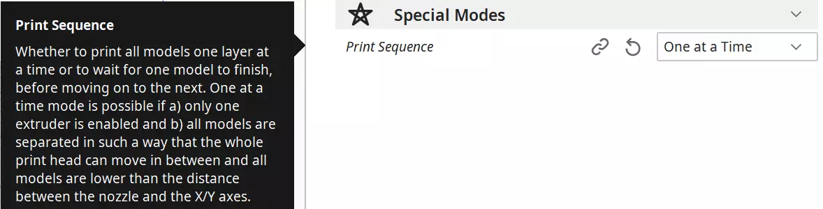
The setting of the print sequence “One at a time” can be found under the special modes.
Printing multiple objects in succession has several advantages:
Less stringing: When you print multiple objects at once, the print head has to move back and forth between objects after each layer. This can result in a lot of stringing. The result is a spider web of filament hairs between the finished models.
But if you print the models one after the other, the print head doesn’t move back and forth between the print objects, but prints one object completely before starting the other. This results in much less stringing.
Fast intervention possible in case of errors: If a systematic error occurs in your models, you will only see it when it is printed on all objects printed at the same time. However, if you print the objects one after the other, you will see the error directly on the first model and can take countermeasures. This way you can save filament.
Shorter print time: The fact that the print head does not have to move back and forth between the simultaneously printed objects is not only good for stringing, it also saves you a lot of print time.
Every movement of the print head that is not spent printing increases the print time. If the objects are printed one at a time, more time is spent printing and less time is spent moving.
But there is also a big disadvantage with this setting: The size of the objects is severely limited.
Especially in Z-direction the size of the print objects is limited. How strong this limitation is, depends on how far the tip of the nozzle is from the lower edge of the X-axis (the frame on which the printhead is mounted) in the Z-direction.
Most of the time this is only a few centimeters. Depending on the 3D printer this value is different but usually never larger than 50 mm.
If you want to print several objects one at a time, you are bound to this value in height. As a conclusion, especially flat objects are perfect for this mode. For example, if you want to print multiple smartphone cases, this setting can make sense.
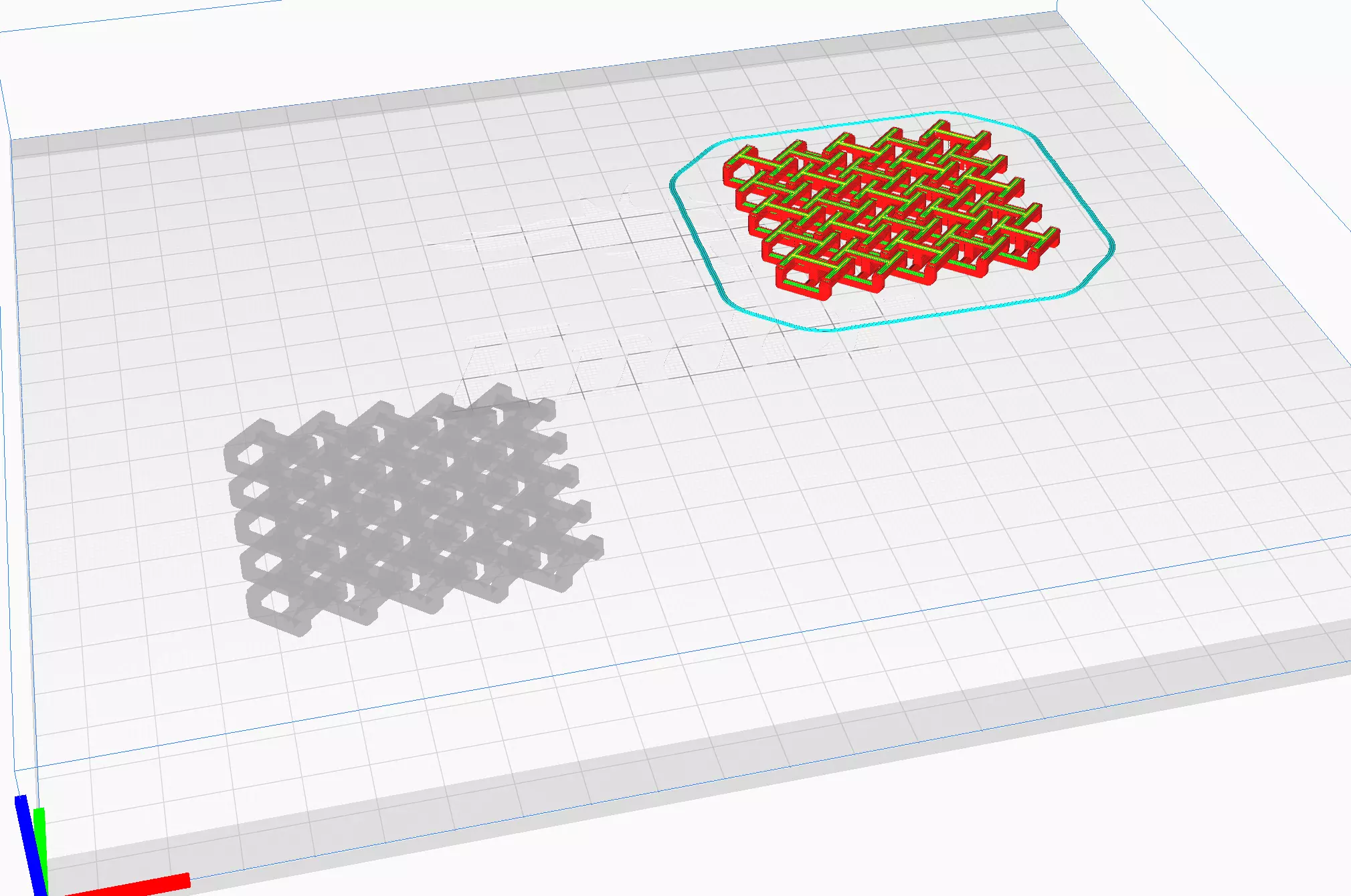
But there are also restrictions in the X and Y direction. Cura shows a shadow around the objects that you have to leave free. The print head needs enough space around the individual objects so that it does not drive into them. To avoid a collision a certain area around the object is reserved.
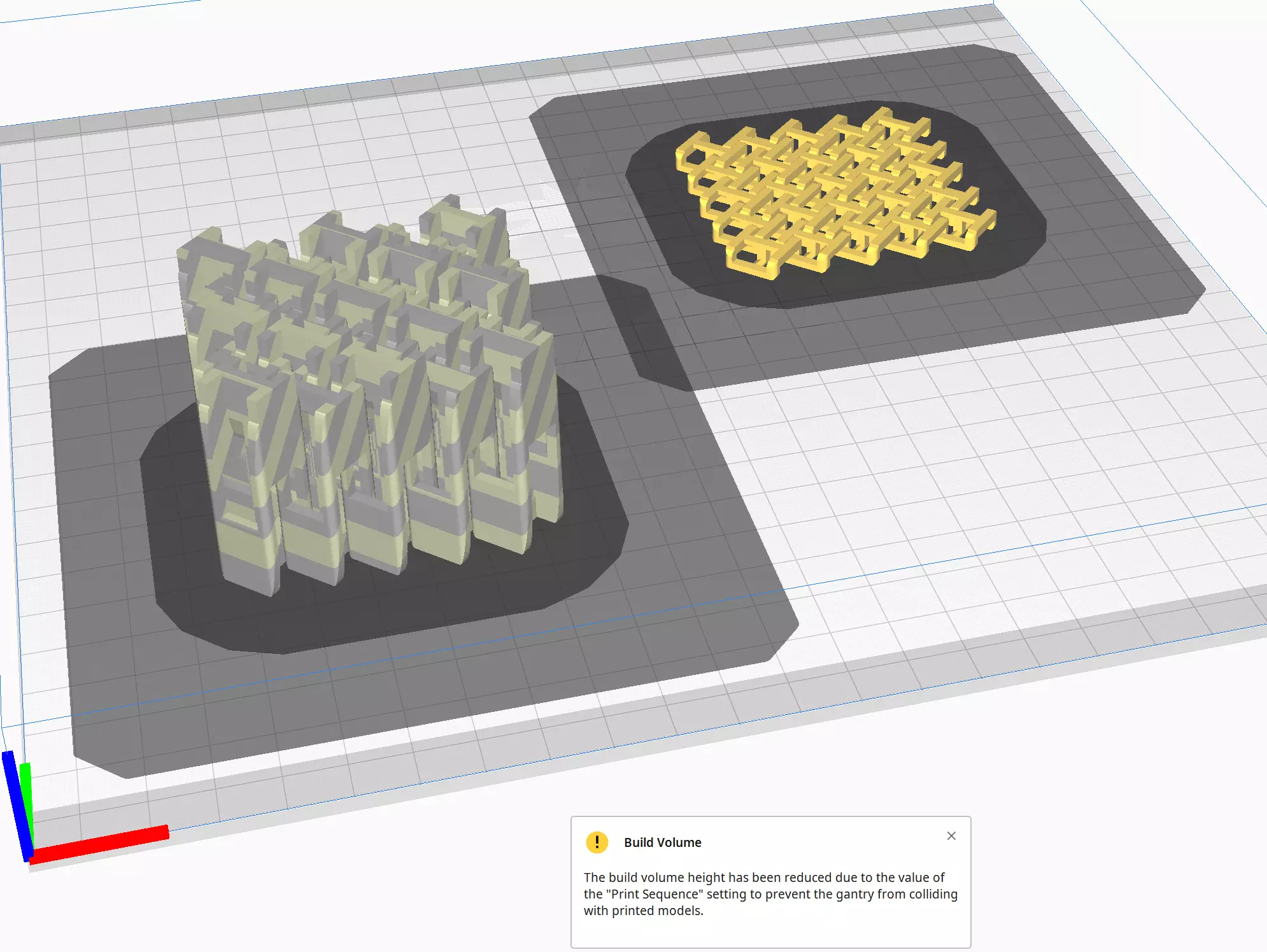
Even if you already know something about Cura, this setting may not be very intuitive. At least, after listing the disadvantages, you probably won’t wonder why most of your objects are grayed out at first and give an error message. They are probably too high.
Here are the steps to make the settings correctly:
- Load the print object
- Under the ‘Special Modes’ select the ‘Print order’ ‘One at a time’.
- Duplicate the print object or load other objects.
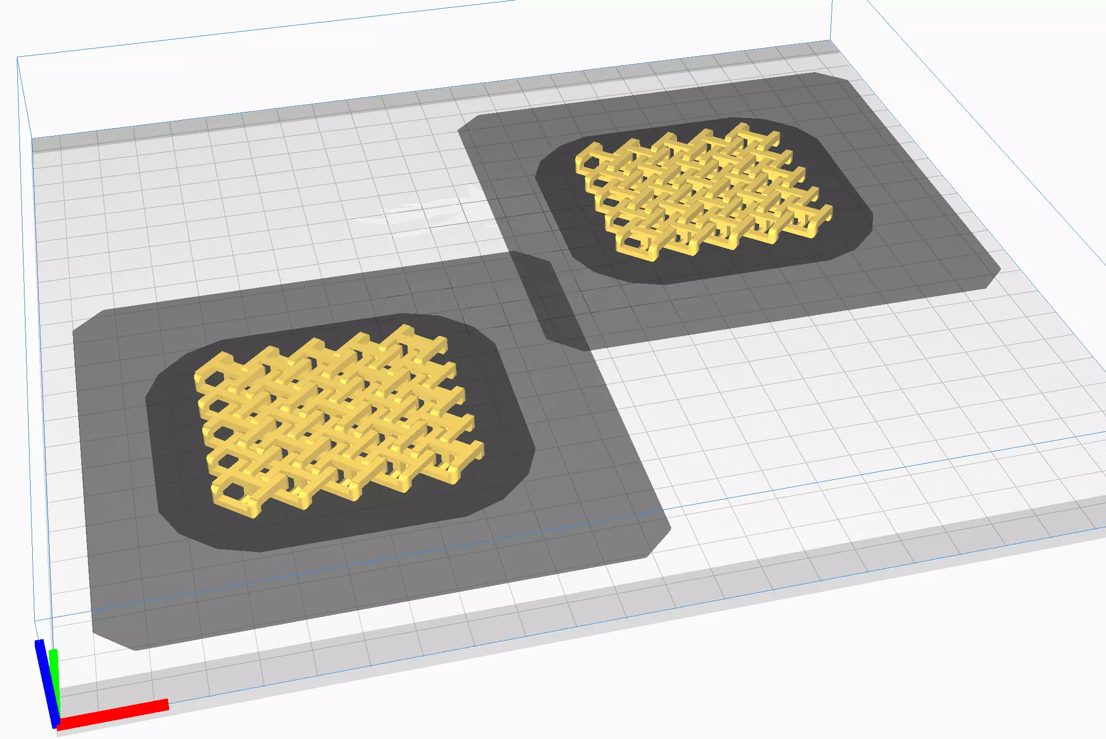
- After the last step, you will see shaded areas around each object. Place the objects so that the shaded area of one object does not touch the first layer of another object.
The shaded area is divided into a lightly shaded area on the outer edge and a heavily shaded area that represents the first layer.
If you have set a skirt, brim, or raft, it will appear as heavily shaded outside the print object. The lightly shaded area must not touch the dark shaded area. The lightly shaded areas may overlap. - Make other print settings and adjust the placement if necessary.
- Slice
- After you have scaled and aligned all objects correctly, you can see under ‘Preview’ in which order the objects will be printed.
Define Printhead Settings
Since you are probably using a pre-built profile in Cura for your 3D printer, you will need to adjust it whenever you modify the printhead. For example, if you install a leveling sensor, new air ducts, or other upgrades that change the size of the printhead, you will need to adjust the settings.
You can find the settings under the device settings of the printers. First open the printer management under ‘Settings’ > ‘Printer’ > ‘Manage printers…’.
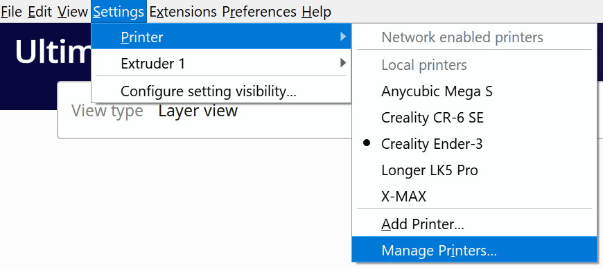
Then click on ‘Machine Settings’.
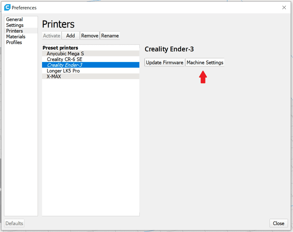
Here you will find the default settings for the printhead on the right side.
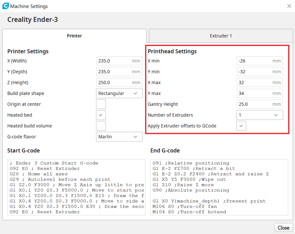
The printhead settings are divided into five main parameters. All parameters are measured from the tip of the nozzle.
- X min: This value determines the left edge of the printhead as seen from the nozzle. The value is always negative because the nozzle is the zero point and is counted to the left into the negative and to the right into the positive.
- Y min: Here you determine the front edge of the print head. This value is also negative, since the Y-axis has its zero point at the front of the 3D printer and is counted up towards the back.
- X max: This value determines the right edge of the printhead as seen from the nozzle. Since the X-axis runs from left to right, this value is positive.
- Y max: This is the rear edge of the printhead as seen from the nozzle. This value is also positive because the Y-axis runs from front to back.
- Gantry Height: This value determines the maximum height of your objects. The value is defined by the perpendicular distance (in Z-direction) of the nozzle to the lowest edge of the X-axis.
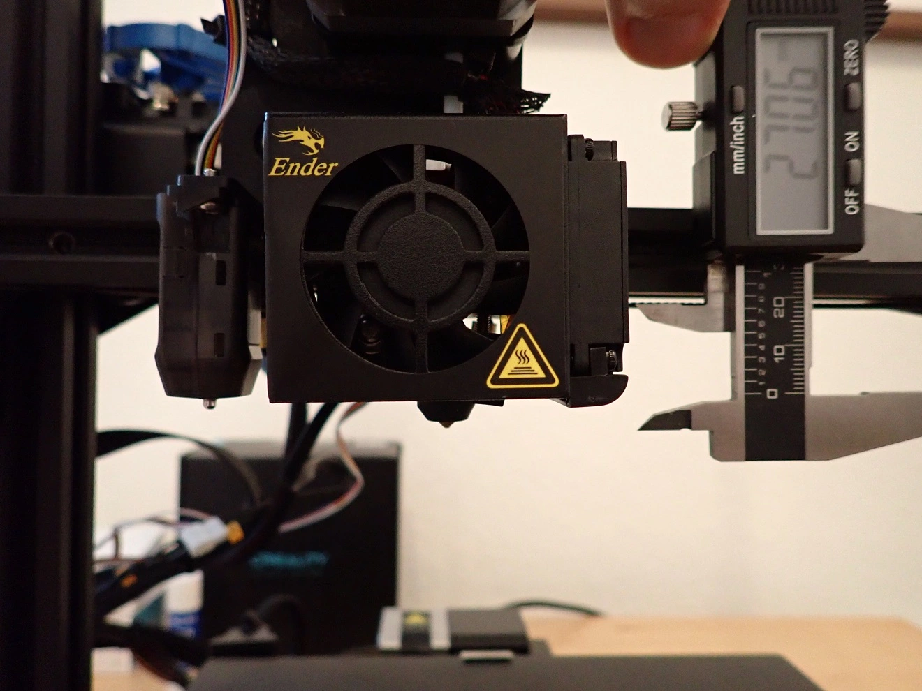
All these values are best determined with a caliper gauge*. If in doubt, a ruler is also fine.
If you use a caliper gauge, do not insert one of the gauge tips into the nozzle! You could damage it and degrade your print quality.
If you are unsure about the measurement, round the value up rather than down. You may lose some space in the XY plane, but you won’t risk collisions. The more precisely you determine the values, the better you can use the space.
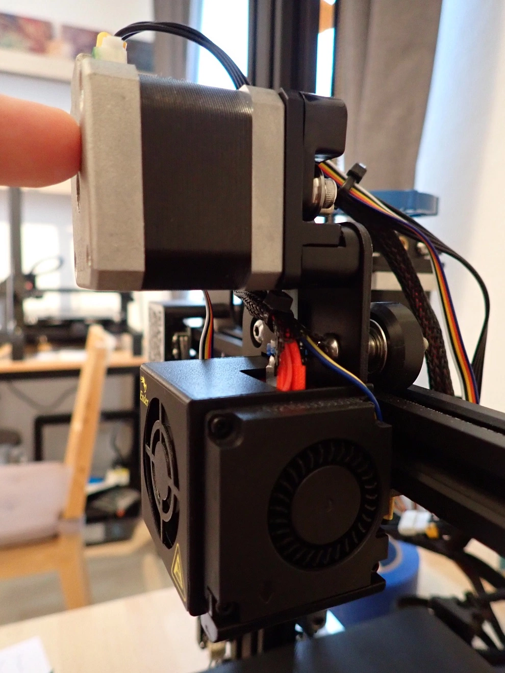
Important: The dimensions of the printhead include all of its components. This includes fans, air ducts, sensors and other attachments that increase the profile of the printhead.
Example: Printhead Settings Ender 3 V2
I upgraded my Ender 3 V2 with a CR-Touch and a Direct-Drive Extruder. Both upgrades change the size of the printhead. The printhead settings need to be adjusted accordingly.
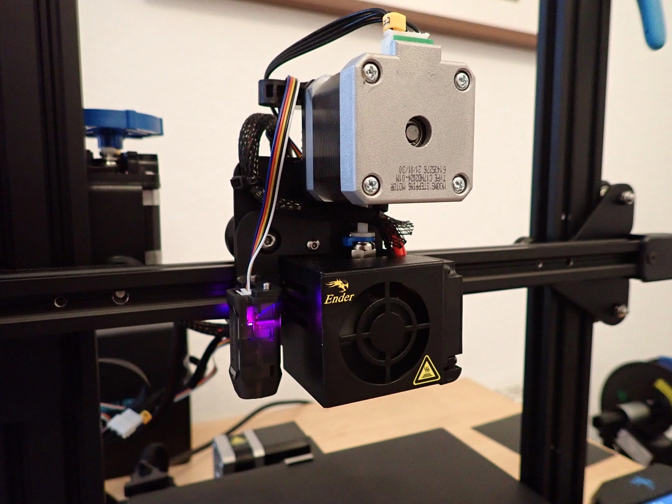
The stepper motor at the top of the print head does not need to be taken into account, as the print objects cannot collide there anyway in the ‘One at a time’ mode. The maximum height of the objects is smaller than the height of the stepper motor.
I used a caliper to measure all the values, rounding sensibly.
| Value | Before | After |
|---|---|---|
| X min | -26 | -53 |
| Y min | -32 | -33 |
| X max | 32 | 31 |
| Y max | 34 | 34 |
| Gantry Height | 25 | 27 |
Gantry Height 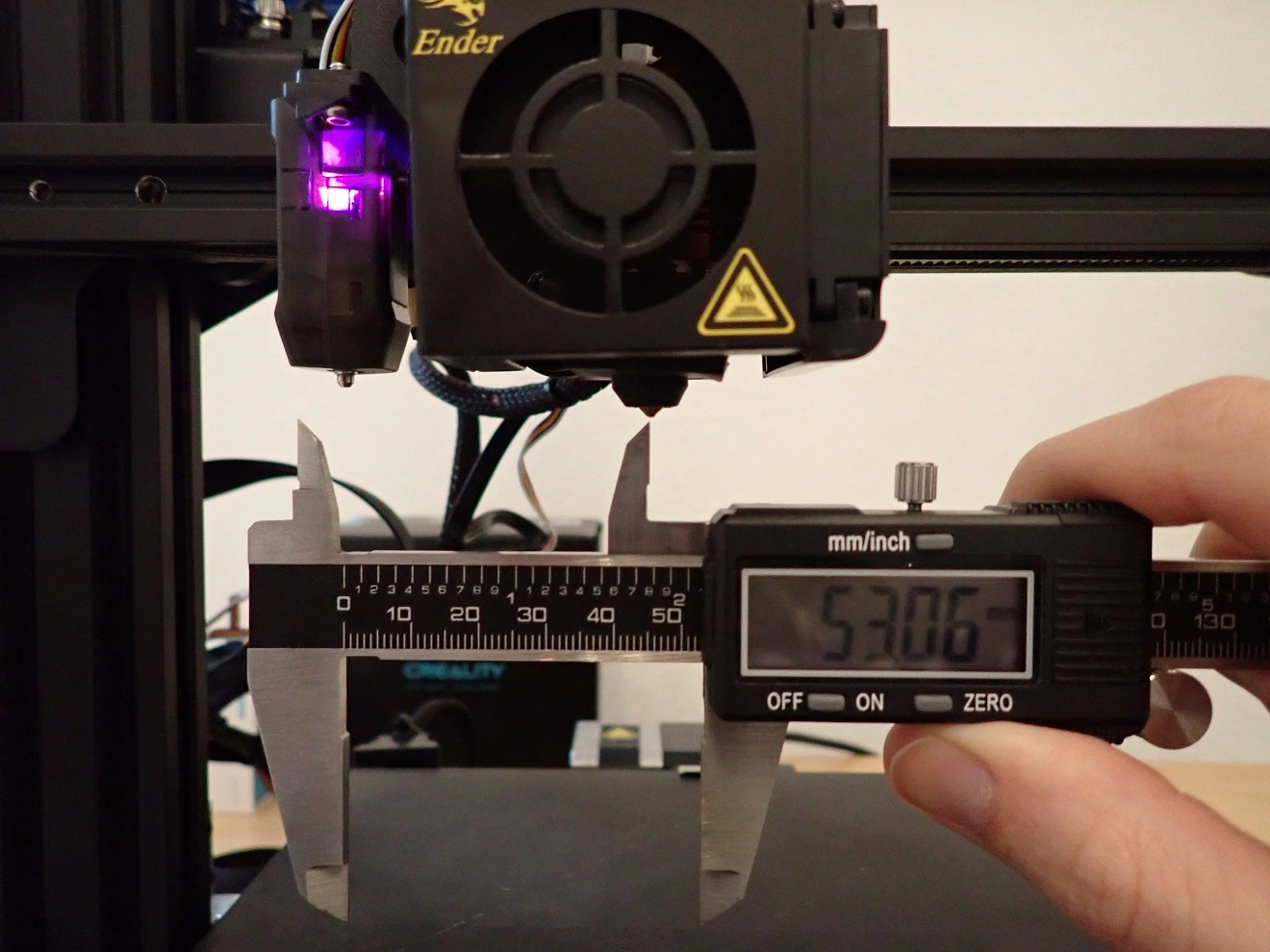
X min 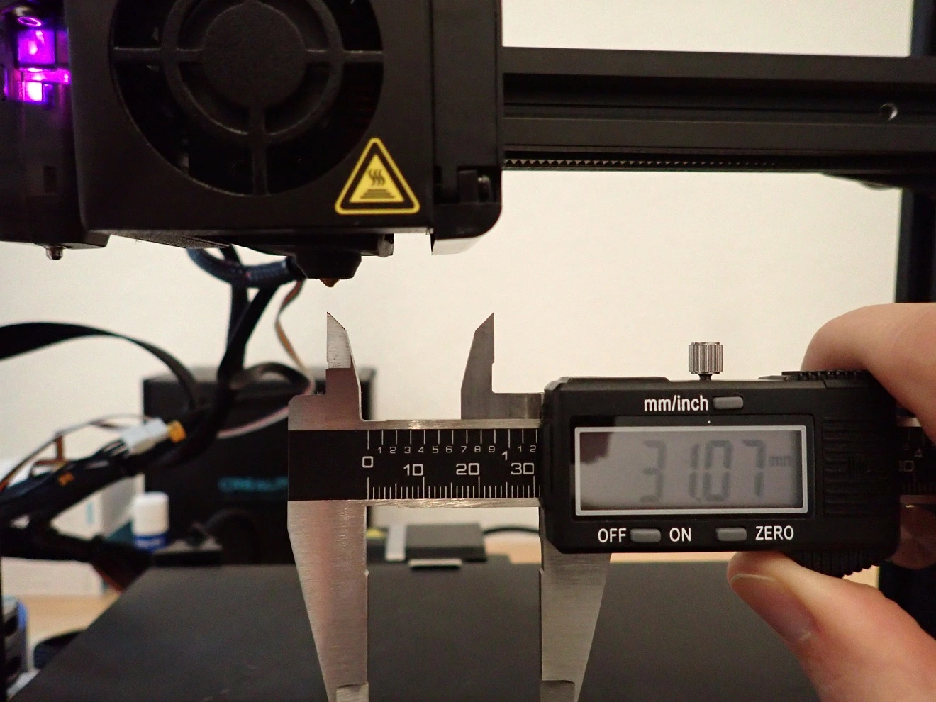
X max 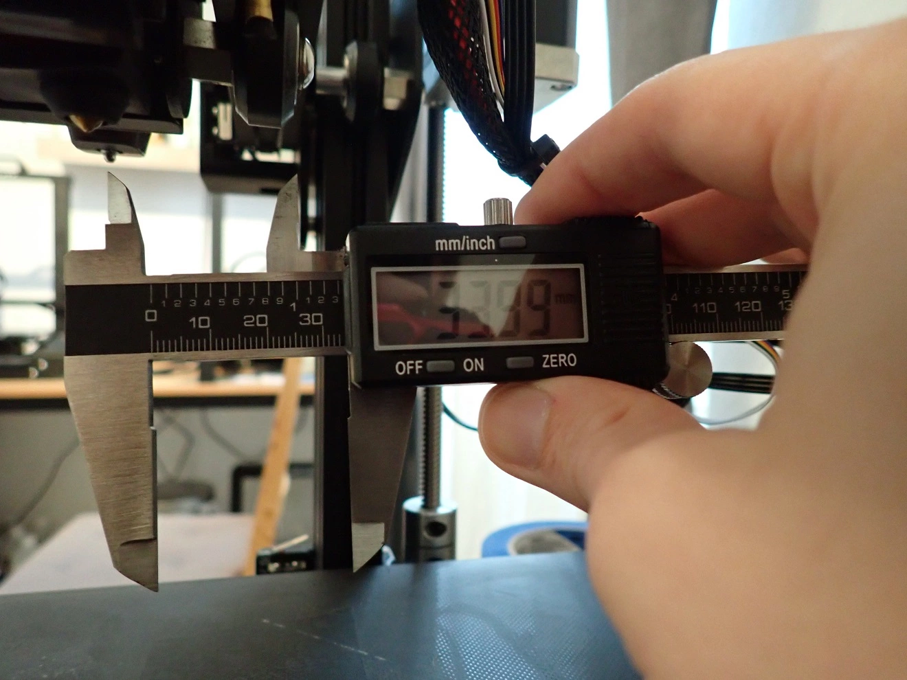
Y max 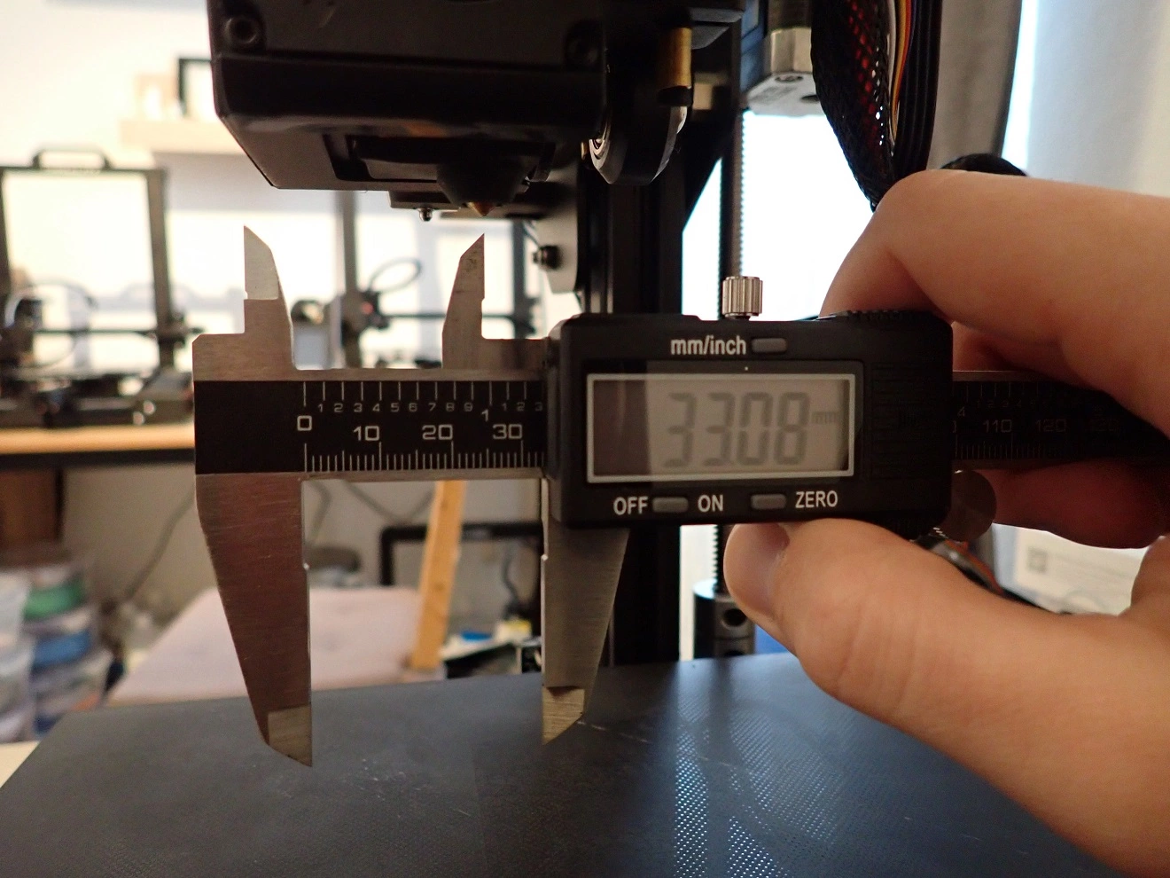
Y min
Due to the CR-Touch especially the X min value has changed a lot. The printhead needs more space due to the leveling sensor on the left side in order not to collide with an already printed model.
Disclosure: This website is the property of Martin Lütkemeyer and is operated by Martin Lütkemeyer. Martin Lütkemeyer is a member of the Amazon Services LLC and other Affiliate Programs. These are affiliate advertising programs designed to enable websites to earn advertising revenue through advertising and linking to Amazon.com and others. Links marked with * are affiliate links.